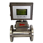
VRGT Gas Turbine Flowmete
A. Features:
1. High precision, good repeatability, low pressure loss, good vibration resistance;
2. Low frictional resistance and good sealing due to being equipped with high quality bearings;
3. It integrates microprocessor, flow sensor, high-precision temperature and pressure sensor to directly measure flow, temperature and pressure of the gas being measured, and automatically performs flow tracking compensation and compression factor correction operation;
4. The instrument has pulse signal or analog signal output, which can directly realize centralized collection and real-time management of computer data through RS485 communication interface or GPRS system;
5. Low power consumption, can be powered by internal batteries, or an external power supply;
6. It has real-time data storage function with which data loss can be prevented when a battery is replaced or suddenly the power supply is in failure. Internal data can be permanently saved during power failure;
7. Can be used with IC card prepaid system for trade settlement;
8. The instrument can be used in dangerous areas. The intrinsically safe explosion proof grade is “Ex ib IIBT4” or “Ex ib IIBT6”.
B. Specification
1. Standard: GB/T 18940-2003 <Measurement of Gas Flow in Closed Pipes - Turbine Flow Meter>
2. Accuracy: +/- 1.0%; +/- 1.5%. Note: Usually flow meters’ accuracy will be +/-1.5% without special notes. Other accuracy is available to be customized on request.
3. Model-Specs-Basic Data Table
| Model | Nominal Diameter DN (mm) | Flowrate Range (m3/h) | Max. Pressure Loss(kPa) | Start-up Flowrate (m3/h) | Installation |
| VRGT - 25A | 25 | 2.5-25 | Negligible | 1 | Flange (or thread) |
| VRGT - 25B | 4-40 | Negligible | 2 | Flange (or thread) | |
| VRGT - 40 | 40 | 4-40 | Negligible | 1.8 | Flange (or thread) |
| VRGT - 50A | 50 | 5-50 | 0.7 | 2.5 | Flange |
| VRGT - 50B | 6-65 | 0.7 | 2.5 | Flange | |
| VRGT - 80A | 80 | 10-100 | 0.3 | 6 | Flange |
| VRGT - 80B | 13-250 | 0.8 | 6 | Flange | |
| VRGT - 100A | 100 | 20-400 | 0.2 | 8 | Flange |
| VRGT - 100B | 36-650 | 0.5 | 8 | Flange | |
| VRGT - 125 | 125 | 35-700 | 0.5 | 12 | Flange |
| VRGT - 150A | 150 | 32-650 | 0.4 | 15 | Flange |
| VRGT - 150B | 50-1000 | 1.7 | 15 | Flange | |
| VRGT - 200A | 200 | 80-1600 | 0.2 | 35 | Flange |
| VRGT - 200B | 130-2500 | 0.9 | 35 | Flange | |
| VRGT - 250A | 250 | 130-2500 | 0.2 | 40 | Flange |
| VRGT - 250B | 200-4000 | 0.5 | 50 | Flange | |
| VRGT - 300 | 300 | 300-6000 | 1.5 | 50 | Flange |
4. Working conditions
Standard state condition: P = 101.325 kPa; T=293.15K
Normal working condition: Ambient temperature: -25℃ - +80℃; Medium temperature: -20℃ - +60℃
Relative humidity: 5 - 95%; Atmospheric pressure: 86kPa - 106kPa
5. Power supply & consumption
a. Power supply: Internal power supply: One piece of lithium battery of 3.6 V DC. The flowmeter can work normally when the voltage is within 3.1 - 3.6 V.
Internal GPRS power supply: One piece of lithium battery of 6.6 V DC. The flowmeter can work normally when the voltage is 5.0 - 6.6 V.
External power supply: 24 V DC +/- 15%, ripple≤+/-5%, be suitable for output of 4 - 20mA, pulse, or RS485, etc.
External power supply (solar energy) GPRS: 5 V DC - 7 V DC
b. Consumption: For external power supplies: less than 1W;
For internal power supply: average consumption≤1mW. One piece of a lithium battery of 3.6 V DC could continuously work for more than 5 years.
For internal GPRS power supply: According to the average number of daily communication (2-12 times), it can work continuously for one to five years.
c. Pulse output: Base meter pulse signals (for calibration to a flow meter): Directly output the raw pulse signal of the base meter detected by the flow sensor through the amplifier, high level≥20 V, low level≤1V;
Corrected working condition pulse signals (or standard volume flow): Set by software, the default is the corrected working condition volume flow pulse output, the amplitude is: high level≥20V, low level≤1V.
Equivalent pulse signals (for IC card controller input): TTL output amplitude 0~3V, output pulse width≥50ms; OC output.
d. Current output: 4-20mA standard analog current output function
In proportion to the standard volume flow, 4mA corresponds to 0 Nm3/h, and 20 mA corresponds to the maximum standard volume flow (this value can be set).
The output form: two-wire system
e. RS485 communication: The internal RS485 standard interface can be connected to a host such as a personal computer or a PLC for serial communication. It can display media pressure, temperature, instantaneous flow, cumulative standard flow, battery voltage, and more.


