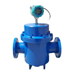
VRHD Helical Double Rotor Flowmeter
Summery
The dual-rotor flowmeter (hereinafter referred to as the flowmeter) is a new type of volumetric flowmeter with unique design and precision machining. A pair of spiral rotors is the only moving body in the metering chamber, which functions to divide, measure, transport and drain the liquid to be measured. This type of flowmeter adds a positioning gear to the structure so that the two rotors do not touch each other when rotating. The flowmeter operates smoothly, has low noise, low wear, high accuracy, and high viscosity adaptability, and can allow a liquid with fine particles to pass, thereby, the rotors can't easily get stuck. The surfaces of the flowmeter wetted parts are treated with electroless nickel plating, so the flowmeter has anti-corrosion and wear-resisting properties and can replace stainless steel flowmeters.
Features
1. It is suitable for thin oil, light oil, heavy oil, crude oil with large sand content and large water content. The viscosity range of the liquids to be measured is large.
2. The flow rate of the liquid passing through the flowmeter is large, and the maximum flow rate is about twice that of the common volume meter of the same diameter.
3. Long service life, high accuracy and high reliability.
4. The internal pressure loss is extremely small.
5. The longest distance of wired remote transmission is 1000 meters, and the pulse signal output is N = 0.1L (one pulse is 1N), which can be directly connected to the computer.
6. Intrinsically safe explosion-proof is Ex iaIICT4.
7. The enclosure protection grade is IP65.
Working principle
As shown in the figure below, the flow meter directly measures the volume of the liquid flow through a pair of rotating special spiral rotors.
The flow meter measures the fluid flow in the metering chamber. A pair of helical rotors rotate under the pressure of the liquid, and the enclosed space (shaded portion) formed between the rotors and the wall of the metering chamber is discharged 8 times of the shadow volume per revolution. Therefore, according to this relationship, as long as the number of revolutions of the rotor is measured, the cumulative amount of flow can be calculated, and the instantaneous flow can be measured according to the number of revolutions per second.
Technical performance
Nominal diameter vs flowrate range table
Nominal | Flowrate range (m3/h) | |||||||||
0.3 mPa.s | 0.3 -2 mPa.s | 2 - 5 | 5 - 15 | 15 - 50 | 50 - 400 | 400 - 1000 | 1000 - 1500 | 1500 - 2000 | ||
LPG | Gasoline | Kerosene | Light diesel | A | B | C | High viscosity liquid | |||
8 | 0.04-0.4 | 0.04-0.4 | 0.04-0.4 | 0.04-0.4 | 0.03-0.3 | 0.03-0.3 | 0.03-0.3 | 0.03-0.3 | ||
15 | 0.25-2.5 | 0.25-2.5 | 0.25-2.5 | 0.3-3.0 | 0.3-3.0 | 0.3-3.0 | 0.3-3.0 | 0.25-1.5 | ||
25 | 0.6-6 | 0.6-6 | 0.6-6 | 0.6-6 | 0.6-6 | 0.6-6 | 0.6-6 | 0.5-5 | 0.5-4 | 0.5-3 |
40 | 5-20 | 4.5-20 | 4-20 | 3-20 | 2.5-20 | 2.5-20 | 2.5-20 | 2-13 | 2-12 | 2-10 |
50 | 6-30 | 5-30 | 5-30 | 4-30 | 4-30 | 4-30 | 3-30 | 2.5-25 | 2.5-20 | 2.5-15 |
80 | 30-80 | 20-80 | 15-80 | 12-80 | 10-80 | 8-80 | 6-80 | 5-55 | 5-45 | 5-39 |
100 | 50-180 | 35-180 | 25-180 | 20-250 | 17-250 | 10-250 | 8.5-250 | 8.5-130 | 8.5-110 | 8.5-97 |
150 | 70-260 | 50-260 | 40-260 | 30-260 | 20-340 | 17-340 | 15-340 | 12-190 | 12-160 | 12-140 |
200 | 100-380 | 70-380 | 55-380 | 45-500 | 35-500 | 30-500 | 25-500 | 25-280 | 25-220 | 25-200 |
250 | 200-630 | 140-630 | 110-630 | 90-800 | 70-800 | 55-800 | 45-800 | 45-460 | 45-380 | 45-340 |
300 | 300-980 | 210-980 | 170-980 | 140-1100 | 110-1100 | 90-110 | 65-1100 | 65-720 | 65-590 | 65-520 |
Note:
| ||||||||||
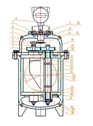
Structure and composition
1. Synchronous gear 
2. Conical pin
3. Conical pin
4. Pinion
5. Screw and pad
6. O-ring
7. Hexagon socket screw
8. Transmitting head
9. Magnetic coupling shaft
10. Connector
11. Gland cover
12. Magnetic coupling gear
13. Cup head screw
14. Upper cover
15. Hexagon screw and washer
16. O-ring
17. Upper cover plate
18. Adjustment pad
19. Cylindrical pin
20. Rotor
21. Active passive rotor shaft
22. Stator
23. Housing
24. Alloy sleeve
25. Lower cover
26. Threaded cylindrical pin
27. Copper sleeve
28. Alloy column
29. Hexagon screw and pad
30. Adjustment screw and female
31. Hexagon socket screw
32. Cylindrical pin
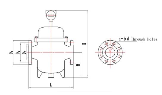
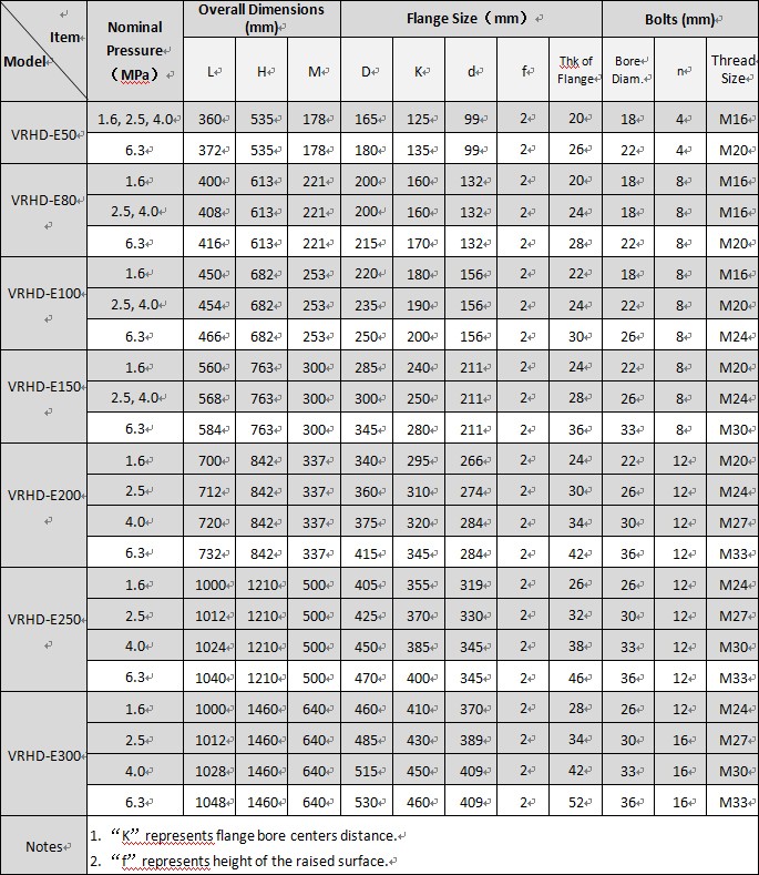
Overall Dimensions


Model Composition
| Basic Model | 1 | 2 | 3 | 4 | 5 | 6 | Description |
| Nominal Dia. mm | Counter | Nominal Press. MPa | Material | Signal Sender | Working Temp. ℃ | ||
| VRHD-E | dual-rotor flowmeter | ||||||
| 8 | Nominal diameter: 8mm | ||||||
| 15 | Nominal diameter: 15mm | ||||||
| 25 | Nominal diameter: 25mm | ||||||
| 40 | Nominal diameter: 40mm | ||||||
| 50 | Nominal diameter: 50mm | ||||||
| 80 | Nominal diameter: 80mm | ||||||
| 100 | Nominal diameter: 100mm | ||||||
| 150 | Nominal diameter: 150mm | ||||||
| 200 | Nominal diameter: 200mm | ||||||
| 250 | Nominal diameter: 250mm | ||||||
| 300 | Nominal diameter: 300mm | ||||||
| W | Only with a pulse transmitter | ||||||
| J | With a mechanical counter | ||||||
| E | With an electronic counter | ||||||
| H | With a mechanical counter that can be reset back to zero | ||||||
| 1.6 | Nominal pressure: 1.6MPa | ||||||
| 2.5 | Nominal pressure: 2.5 MPa | ||||||
| 4.0 | Nominal pressure: 4.0 MPa | ||||||
| 6.3 | Nominal pressure: 6.3 MPa | ||||||
| C304 | Rotors material is stainless steel 304 | ||||||
| C316 | Rotors material is stainless steel 316 | ||||||
| CC304 | The material of rotor and housing is stainless steel 304 | ||||||
| CC316 | The material of rotor and housing is stainless steel 316 | ||||||
| F | Pulse output | ||||||
| I | Current output | ||||||
| A | Working temperature: -20℃- +80℃ | ||||||
| B | Working temperature: -20℃- +150℃ | ||||||
| C | Working temperature: -20℃- +250℃ | ||||||
| D | Working temperature: -20℃- +350℃ |


